Easy, Affordable Financing Available Now!
Apply NowBrillion Rigid Shear Bolt Shanks, Non-Folding Units

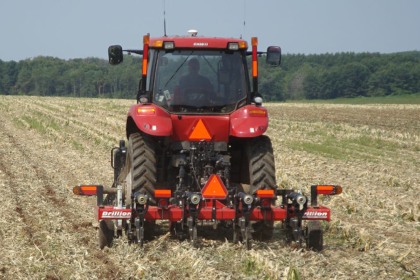
Zone Commander Rigid Shear Bolt Shanks, Non-Folding Units
The Brillion Zone Commander is a compaction management tool designed to address soil compaction issues within the growth profile in a controlled manner in a defined area. Designed from the ground up to meet the requirements of compaction control with minimal surface disturbance, the Zone Commander has developed the rep... + Read More
Features
Rugged and Durable
All tillage tools need to be built to handle the stress of the fast-paced industry of today. However, deep tillage machines with depth capacities well below the normal operating depths need to be especially tough. In many instances, these tools will be operating in profiles that have never been touched by a tillage tool before. The Zone Commander has what it takes.
The Frame
Built with 6” x 4” structural steel tubing, the robotically welded frame is the foundation for the heavy-duty Cat. II, III or IV three-point hitch. The robust frame is the anchor for the lead colters that start the tillage process. The rear bar of the frame supports the Zone Commander’s shank assemblies.
The Shank Mount
The Zone Commander shank mounts are built to withstand the rigorous torture that operating in unknown soil profiles can dish out. The auto-reset shank assemblies allow for 3,500 lbs. of point load and 17” of trip height. Rigid shear bolt models are also available for areas with minimal soil obstructions.
The Shank Leg
The heart and soul of the Zone Commander is the shank leg, which cuts a narrow slot into the soil profile. The geometry of the shank leg and the shape of the point combine to lift and lower the soil between the slots and develop a network of horizontal cracks and breaks between the shanks. This slot along with the cracks and breaks created in the growth profile allows water and oxygen to infiltrate the soil to enhance plant growth for the next season. The depth of the slot is determined by how deep and thick the compaction layer is. This process is instrumental in keeping the biological environment favorable for residue decomposition.
Versatility in Options
The Zone Commander can be equipped with either auto-reset shank assemblies or rigid shear bolt shanks. Shank leg options include the 1 ¼” straight leg, the 1 ¼” parabolic leg, or the ¾” low disturbance shank. Spring cushion lead coulters with different blade options cut the residue and slice the upper layers in the soil profile ahead of the shanks. Easily adjustable gauge wheels allow for quick, positive depth changes for different conditions. The Zone Commander is available in 3 to 7 shank non-folding models and in 7, 8 and 9 shank folding models.
Your Investment
The Zone Commander is more than just another ripper. The Zone Commander can be an integral part of almost any type of cropping scenario. Even though these machines were initially designed for deep in-line tillage, some customers use the Zone Commander for incorporation practices such as sludge and manure application. Others have utilized the parabolic shank leg option for more disturbance on the soil surface. Still, others have opted for the low disturbance shank legs for the absolute least amount of surface disturbance. From true no-tillers to conventional tillage aficionados, the Zone Commander and its concept of compaction management is a yield enhancement investment.
The Brillion Zone Commander…one machine…widely diversified…your investment.
Specs
| Product Attributes | 2511ZCR-3N | 2511ZCR-4N | 2511ZCR-5N | 2512ZCR-5 | 2512ZCR-6 | 2512ZCR-7 |
| Approximate Weight | 2,410 lbs. (1,093 kg) | 2,735 lbs. (1,241 kg) | 3,345 lbs. (1,517 kg) | 5,573 lbs. (2,528 kg) | 7,219 lbs. (3,274 kg) | 8,251 lbs. (3,743 kg) |
| Working Width | 7 ft. 6 in. (2.3 m) | 10 ft. 0 in. (3.0 m) | 12 ft. 6 in. (3.8 m) | 12 ft. 6 in. (3.8 m) | 15 ft. 0 in. (4.6 m) | 17 ft. 6 in. (5.3 m) |
| Transport Width | 9 ft. 3 in. (2.8 m) | 9 ft. 3 in. (2.8 m) | 12 ft. 0 in. (3.7 m) | 11 ft. 6 in. (3.5 m) | 13 ft. 5 in. (4.1 m) | 15 ft. 11 in. (4.9 m) |
| Frame Type | Narrow Non-Folding | Narrow Non-Folding | Narrow Non-Folding | Standard Non-Folding | Standard Non-Folding | Standard Non-Folding |
| Frame Structure | 6 in. x 4 in. (152 x 102 mm) Double Bar Frame | 6 in. x 4 in. (152 x 102 mm) Double Bar Frame | 6 in. x 4 in. (152 x 102 mm) Double Bar Frame | 6 in. x 6 in. x 0.5 in. (152 x 152 x 13 mm) Rear Frame 6 in. x 4 in. x 0.5 in. (152 x 102 x 13 mm) Front Frame | 6 in. x 6 in. x 0.5 in. (152 x 152 x 13 mm) Rear Frame 6 in. x 4 in. x 0.5 in. (152 x 102 x 13 mm) Front Frame | 6 in. x 6 in. x 0.5 in. (152 x 152 x 13 mm) Rear Frame 6 in. x 4 in. x 0.5 in. (152 x 102 x 13 mm) Front Frame |
| Frame Construction | Laser Cut Components; Robotically Welded | Laser Cut Components; Robotically Welded | Laser Cut Components; Robotically Welded | Laser Cut Components; Robotically Welded | Laser Cut Components; Robotically Welded | Laser Cut Components; Robotically Welded |
| Frame Extensions | None | None | 12 in. (305 mm) Bolt-On | None | 12 in. (305 mm) Bolt-On | 27 in. (686 mm) Bolt-On |
| Coulter Assemblies | Standard | Standard | Standard | Standard | Standard | Standard |
| Number of Coulters | 3 | 4 | 5 | 5 | 6 | 7 |
| Coulter Blade Diameter | 22 in. (559 mm) Smooth Blade (Standard) | 22 in. (559 mm) Smooth Blade (Standard) | 22 in. (559 mm) Smooth Blade (Standard) | 22 in. (559 mm) Smooth Blade (Standard) | 22 in. (559 mm) Smooth Blade (Standard) | 22 in. (559 mm) Smooth Blade (Standard) |
| Coulter Protection | Adjustable Spring Cushion | Adjustable Spring Cushion | Adjustable Spring Cushion | Adjustable Spring Cushion | Adjustable Spring Cushion | Adjustable Spring Cushion |
| Coulter Down Pressure | 600 lbs. (272 kg) | 600 lbs. (272 kg) | 600 lbs. (272 kg) | 600 lbs. (272 kg) | 600 lbs. (272 kg) | 600 lbs. (272 kg) |
| Coulter Trip Height | 6 in. (152 mm) | 6 in. (152 mm) | 6 in. (152 mm) | 6 in. (152 mm) | 6 in. (152 mm) | 6 in. (152 mm) |
| 22 in. Ripple Coulter | Optional | Optional | Optional | Optional | Optional | Optional |
| 22 in. Pyramid Coulter | Optional | Optional | Optional | Optional | Optional | Optional |
| Number of Shanks | 3 | 4 | 5 | 5 | 6 | 7 |
| Shank Type | Rigid Shear Bolt Shank | Rigid Shear Bolt Shank | Rigid Shear Bolt Shank | Rigid Shear Bolt Shank | Auto-Reset Spring Shank | Rigid Shear Bolt Shank |
| Shear Bolt Size | 0.625 in. x 3.5 in. (16 x 89 mm) Grade 8 | 0.625 in. x 3.5 in. (16 x 89 mm) Grade 8 | 0.625 in. x 3.5 in. (16 x 89 mm) Grade 8 | 0.625 in. x 3.5 in. (16 x 89 mm) Grade 8 | 0.625 in. x 3.5 in. (16 x 89 mm) Grade 8 | 0.625 in. x 3.5 in. (16 x 89 mm) Grade 8 |
| Shank Leg Type* | 1.25 in. x 5 in. x 36 in. (32.8 x 127 x 914 mm) Straight Leg Shank | 1.25 in. x 5 in. x 36 in. (32.8 x 127 x 914 mm) Straight Leg Shank | 1.25 in. x 5 in. x 36 in. (32.8 x 127 x 914 mm) Straight Leg Shank | 1.25 in. x 5 in. x 36 in. (32.8 x 127 x 914 mm) Straight Leg Shank | 1.25 in. x 5 in. x 36 in. (32.8 x 127 x 914 mm) Straight Leg Shank | 1.25 in. x 5 in. x 36 in. (32.8 x 127 x 914 mm) Straight Leg Shank |
| 1.25 in. x 4 in. x 36 in. (32.8 x 102 x 914 mm) Parabolic Shank | 1.25 in. x 4 in. x 36 in. (32.8 x 102 x 914 mm) Parabolic Shank | 1.25 in. x 4 in. x 36 in. (32.8 x 102 x 914 mm) Parabolic Shank | 1.25 in. x 4 in. x 36 in. (32.8 x 102 x 914 mm) Parabolic Shank | 1.25 in. x 4 in. x 36 in. (32.8 x 102 x 914 mm) Parabolic Shank | 1.25 in. x 4 in. x 36 in. (32.8 x 102 x 914 mm) Parabolic Shank | |
| 0.75 in. x 5 in. x 32 in. (19 x 127 x 813 mm) Low Disturbance Shank | 0.75 in. x 5 in. x 32 in. (19 x 127 x 813 mm) Low Disturbance Shank | 0.75 in. x 5 in. x 32 in. (19 x 127 x 813 mm) Low Disturbance Shank | 0.75 in. x 5 in. x 32 in. (19 x 127 x 813 mm) Low Disturbance Shank | 0.75 in. x 5 in. x 32 in. (19 x 127 x 813 mm) Low Disturbance Shank | 0.75 in. x 5 in. x 32 in. (19 x 127 x 813 mm) Low Disturbance Shank | |
| Shank Spacing | 30 in. (762 mm) | 30 in. (762 mm) | 30 in. (762 mm) | 30 in. (762 mm) | 30 in. (762 mm) | 30 in. (762 mm) |
| Maximum Shank Working Depth | 20 in. (508 mm) | 20 in. (508 mm) | 20 in. (508 mm) | 20 in. (508 mm) | 20 in. (508 mm) | 20 in. (508 mm) |
| Under Frame Clearance | 40.5 in. (1.0 m) | 40.5 in. (1.0 m) | 40.5 in. (1.0 m) | 40.5 in. (1.0 m) | 40.5 in. (1.0 m) | 40.5 in. (1.0 m) |
| Points for Straight Leg Shanks | 2 in. (50.8 mm) V-Shaped Cast C.A.D.I. Point (Standard) | 2 in. (50.8 mm) V-Shaped Cast C.A.D.I. Point (Standard) | 2 in. (50.8 mm) V-Shaped Cast C.A.D.I. Point (Standard) | 2 in. (50.8 mm) V-Shaped Cast C.A.D.I. Point (Standard) | 2 in. (50.8 mm) V-Shaped Cast C.A.D.I. Point (Standard) | 2 in. (50.8 mm) V-Shaped Cast C.A.D.I. Point (Standard) |
| Wearstrips for Straight Leg Shanks | C.A.D.I. Reversible Wearstrip (Standard) | C.A.D.I. Reversible Wearstrip (Standard) | C.A.D.I. Reversible Wearstrip (Standard) | C.A.D.I. Reversible Wearstrip (Standard) | C.A.D.I. Reversible Wearstrip (Standard) | C.A.D.I. Reversible Wearstrip (Standard) |
| Points for Parabolic Shanks | 2.375 in. (60.3 mm) V-Cap C.A.D.I. Point (Standard) | 2.375 in. (60.3 mm) V-Cap C.A.D.I. Point (Standard) | 2.375 in. (60.3 mm) V-Cap C.A.D.I. Point (Standard) | 2.375 in. (60.3 mm) V-Cap C.A.D.I. Point (Standard) | 2.375 in. (60.3 mm) V-Cap C.A.D.I. Point (Standard) | 2.375 in. (60.3 mm) V-Cap C.A.D.I. Point (Standard) |
| Shark Fin Point (Optional) | Shark Fin Point (Optional) | Shark Fin Point (Optional) | Shark Fin Point (Optional) | Shark Fin Point (Optional) | Shark Fin Point (Optional) | |
| 7 in. (178 mm) Wing Point (Optional) | 7 in. (178 mm) Wing Point (Optional) | 7 in. (178 mm) Wing Point (Optional) | 7 in. (178 mm) Wing Point (Optional) | 7 in. (178 mm) Wing Point (Optional) | 7 in. (178 mm) Wing Point (Optional) | |
| Wearstrips for Parabolic Shanks | C.A.D.I. Wearstrip (Standard) | C.A.D.I. Wearstrip (Standard) | C.A.D.I. Wearstrip (Standard) | C.A.D.I. Wearstrip (Standard) | C.A.D.I. Wearstrip (Standard) | C.A.D.I. Wearstrip (Standard) |
| Points for Low Disturbance Shanks | 2 in. (50.8 mm) V-Shaped Cast Point (Standard) | 2 in. (50.8 mm) V-Shaped Cast Point (Standard) | 2 in. (50.8 mm) V-Shaped Cast Point (Standard) | 2 in. (50.8 mm) V-Shaped Cast Point (Standard) | 2 in. (50.8 mm) V-Shaped Cast Point (Standard) | 2 in. (50.8 mm) V-Shaped Cast Point (Standard) |
| Wearstrips for Low Disturbance Shanks | 0.75 in. (19 mm) Wearstrip (Standard) | 0.75 in. (19 mm) Wearstrip (Standard) | 0.75 in. (19 mm) Wearstrip (Standard) | 0.75 in. (19 mm) Wearstrip (Standard) | 0.75 in. (19 mm) Wearstrip (Standard) | 0.75 in. (19 mm) Wearstrip (Standard) |
| Gauge Wheels | (2) Standard | (2) Standard | (2) Standard | (2) Standard | (2) Standard | (2) Standard |
| Gauge Wheel Type | Turnbuckle Adjustable | Turnbuckle Adjustable | Turnbuckle Adjustable | Turnbuckle Adjustable | Turnbuckle Adjustable | Turnbuckle Adjustable |
| Gauge Wheel Hubs | 6-Bolt | 6-Bolt | 6-Bolt | 6-Bolt | 6-Bolt | 6-Bolt |
| Gauge Wheel Tire Size | HD 280/70R x 15 | HD 280/70R x 15 | HD 280/70R x 15 | HD 280/70R x 15 | HD 280/70R x 15 | HD 280/70R x 15 |
| Three-Point Hitch | Cat. II, IIIN | Cat. II, IIIN | Cat. II, IIIN | Cat. III, IV | Cat. III, IV | Cat. III, IV |
| Coverboard Kit | Optional | Optional | Optional | Optional | Optional | Optional |
| 12 in. Offset Shank Mounts | Optional | Optional | Optional | Optional | Optional | Optional |
| Pull-Hitch Caddy | N/A | N/A | N/A | Optional | Optional | Optional |
| Rear Hitch | N/A | Optional | Optional | Optional | Optional | Optional |
| Parking Stands | Standard | Standard | Standard | Standard | Standard | Standard |
| Powder Coat Paint, Red | Standard | Standard | Standard | Standard | Standard | Standard |
| LED Warning Lights & SMV Emblem | Standard | Standard | Standard | Standard | Standard | Standard |
| Horsepower Requirements | 40 HP and up (30 kW) Per Shank | 40 HP and up (30 kW) Per Shank | 40 HP and up (30 kW) Per Shank | 40 HP and up (30 kW) Per Shank | 40 HP and up (30 kW) Per Shank | 40 HP and up (30 kW) Per Shank |
| Recommended Operating Speed | 3 to 5 MPH (4.8 to 8.0 km/h) | 3 to 5 MPH (4.8 to 8.0 km/h) | 3 to 5 MPH (4.8 to 8.0 km/h) | 3 to 5 MPH (4.8 to 8.0 km/h) | 3 to 5 MPH (4.8 to 8.0 km/h) | 3 to 5 MPH (4.8 to 8.0 km/h) |
*Units are equipped with choice of Straight Leg Shanks, Parabolic Shanks or Low Disturbance Shanks. Points and Wearstrips listed as Standard are included with each respective shank choice, unless Optional equipment is chosen.
Copyright © 2024 - All Rights Reserved - EquipmentLocator.com


